CNC Machining
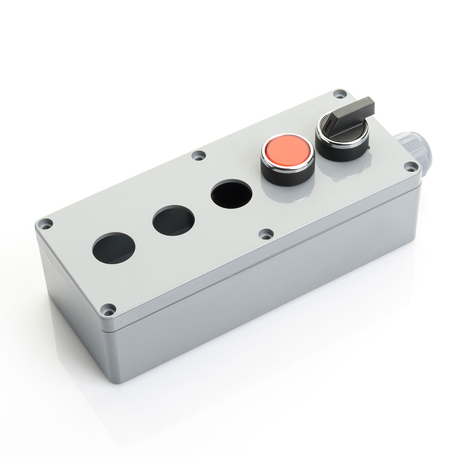
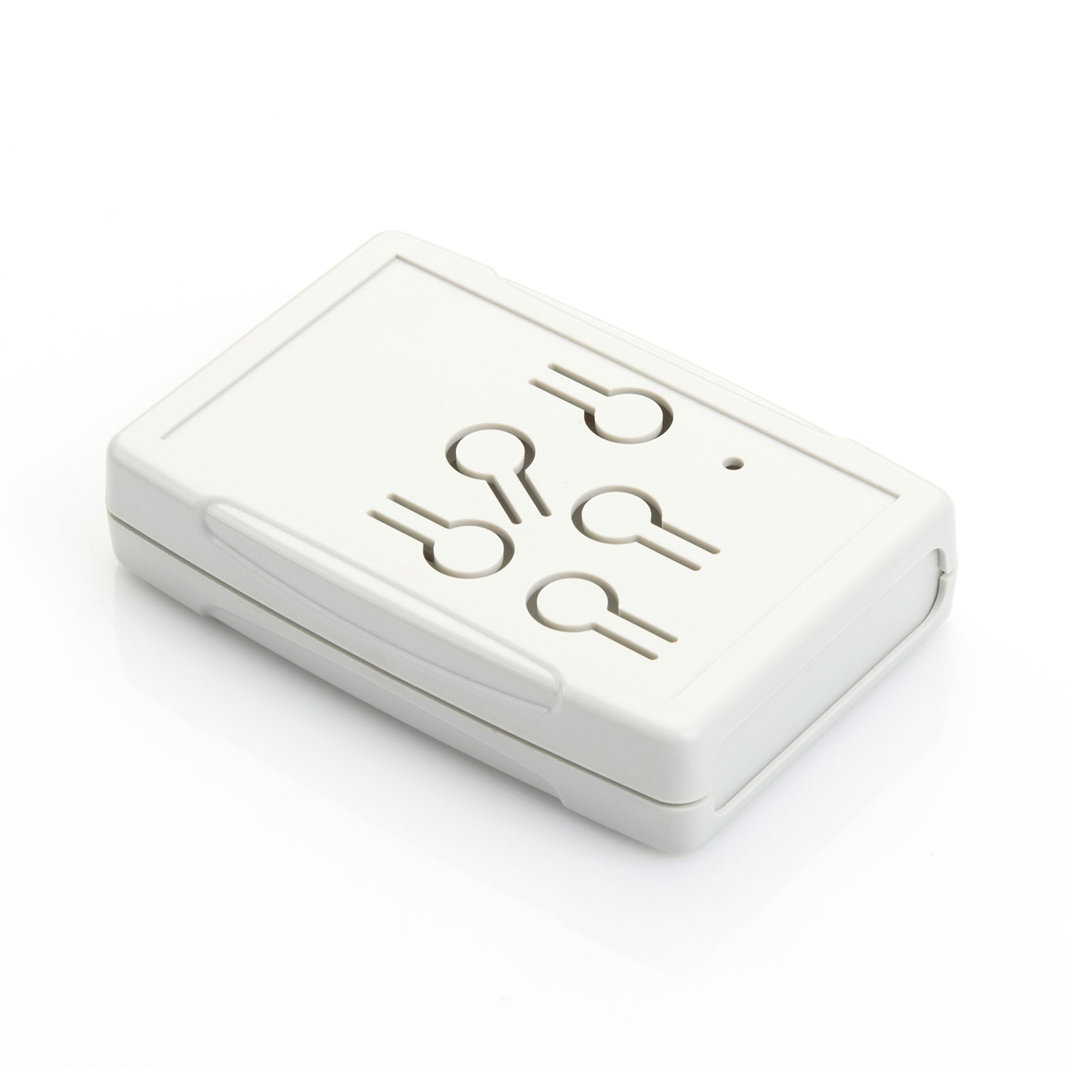
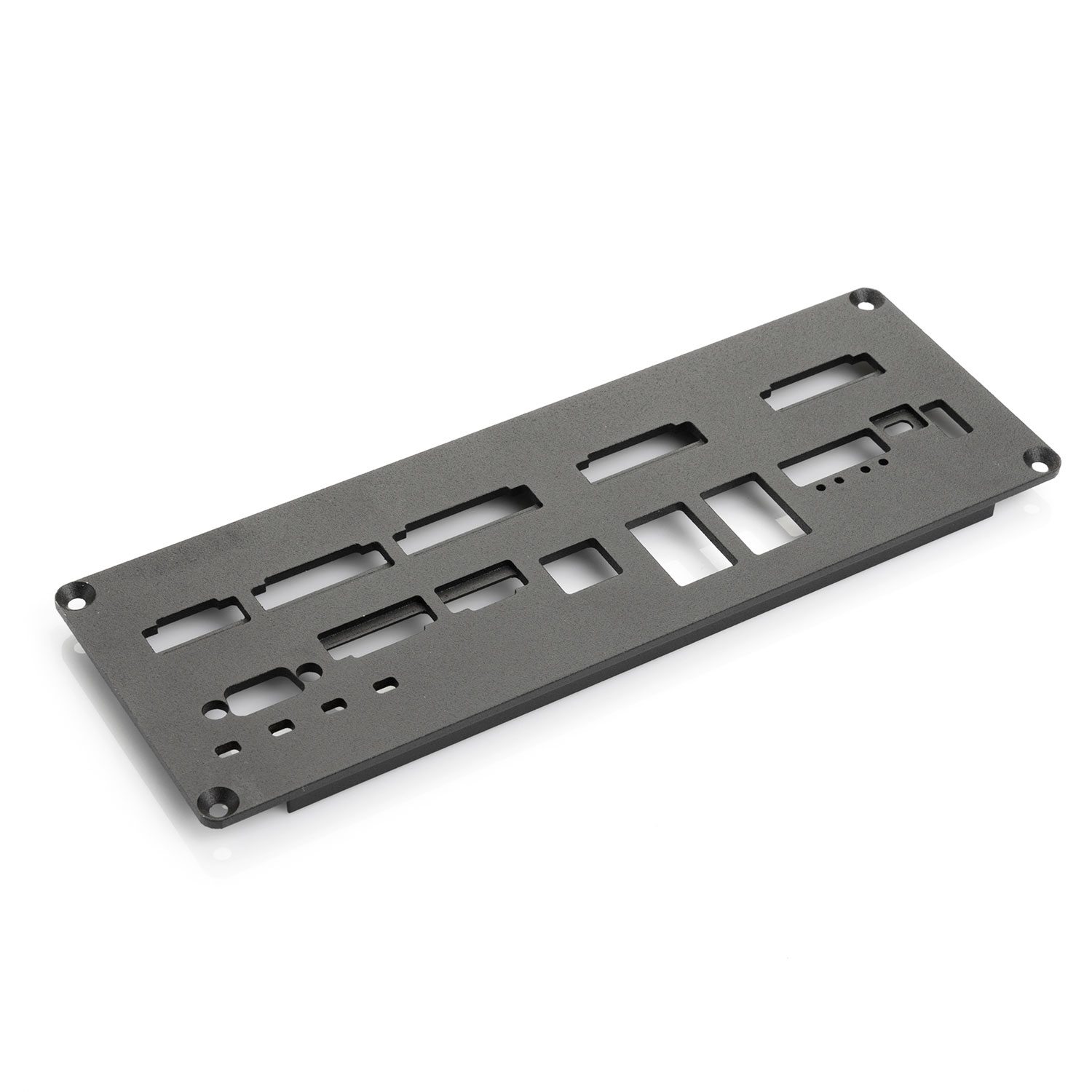
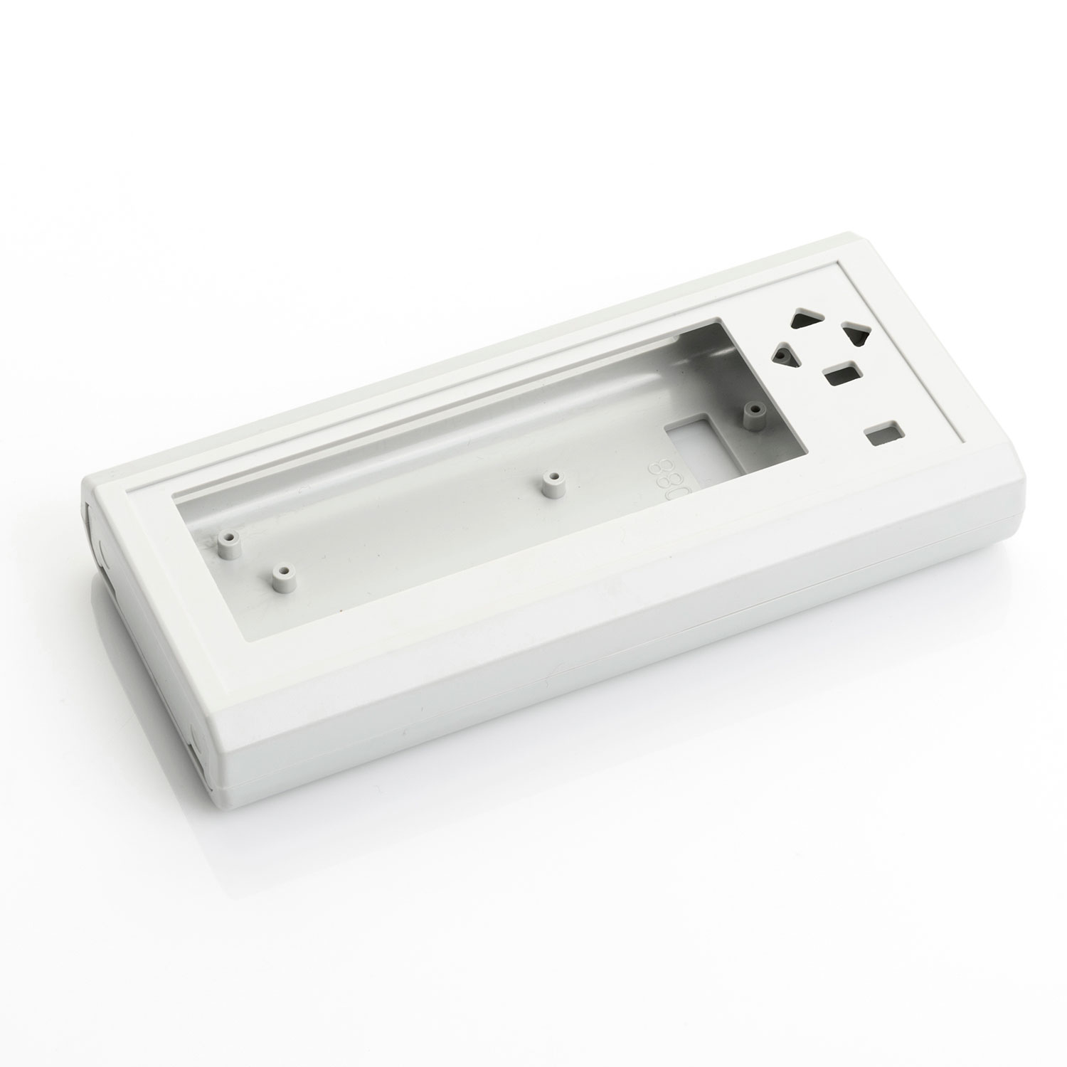
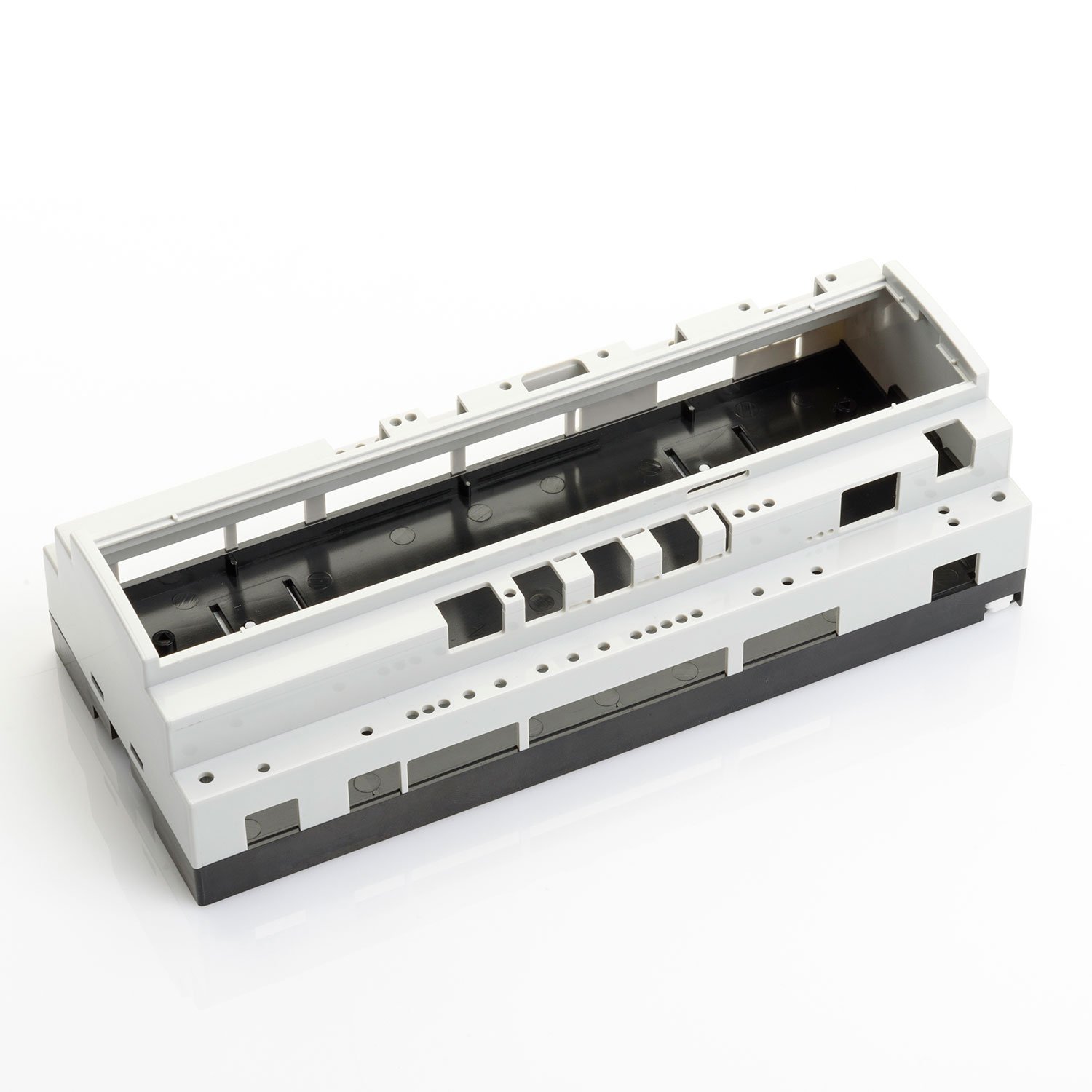
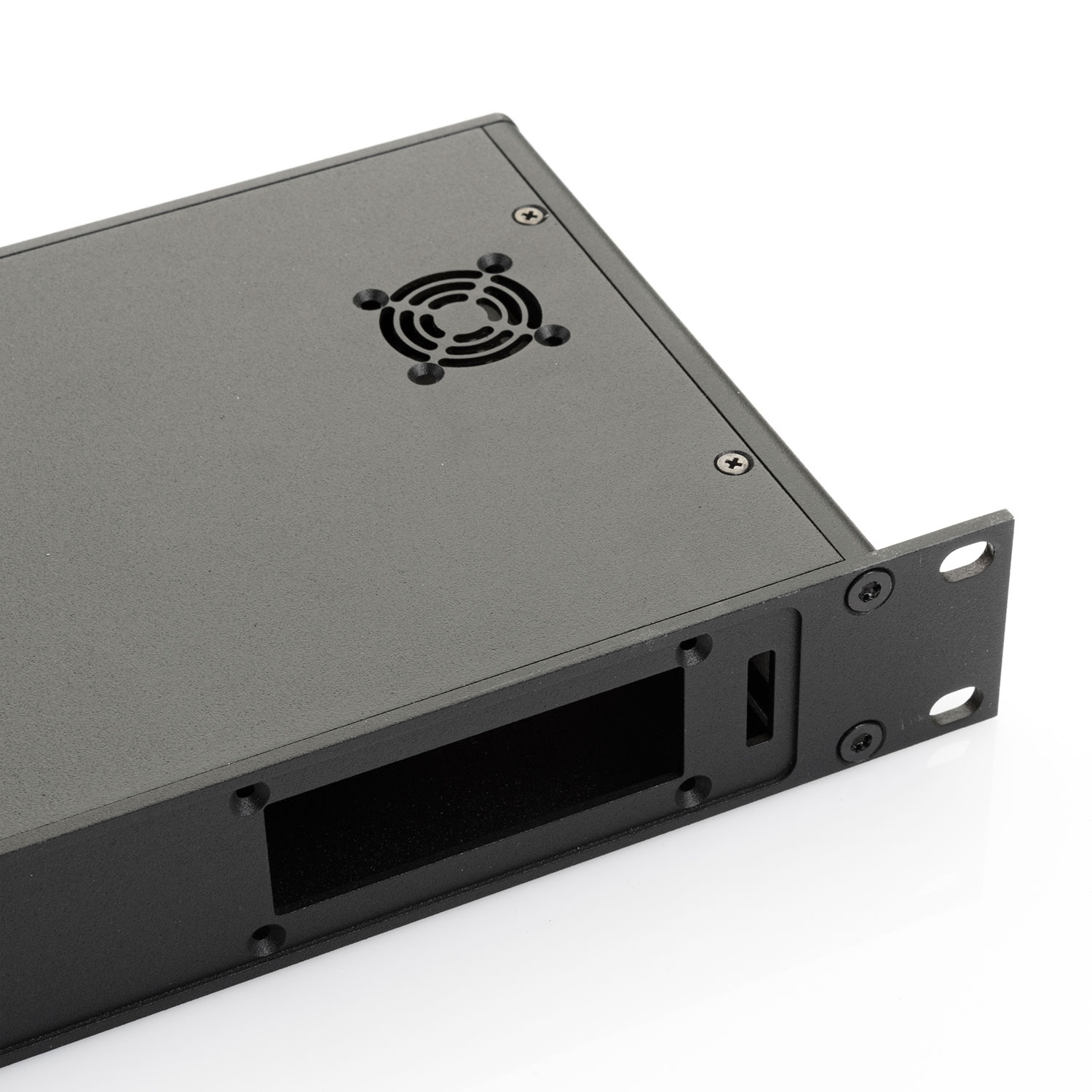
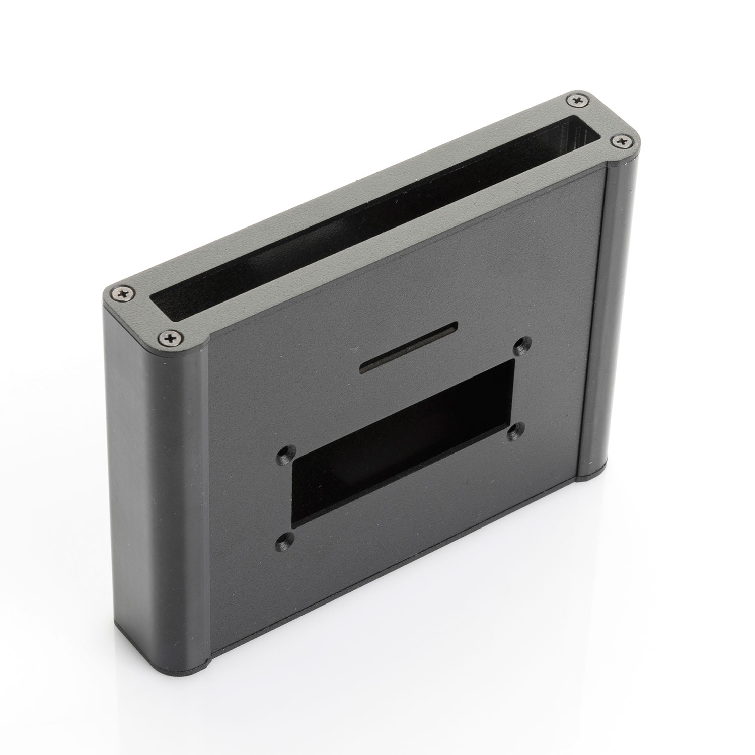
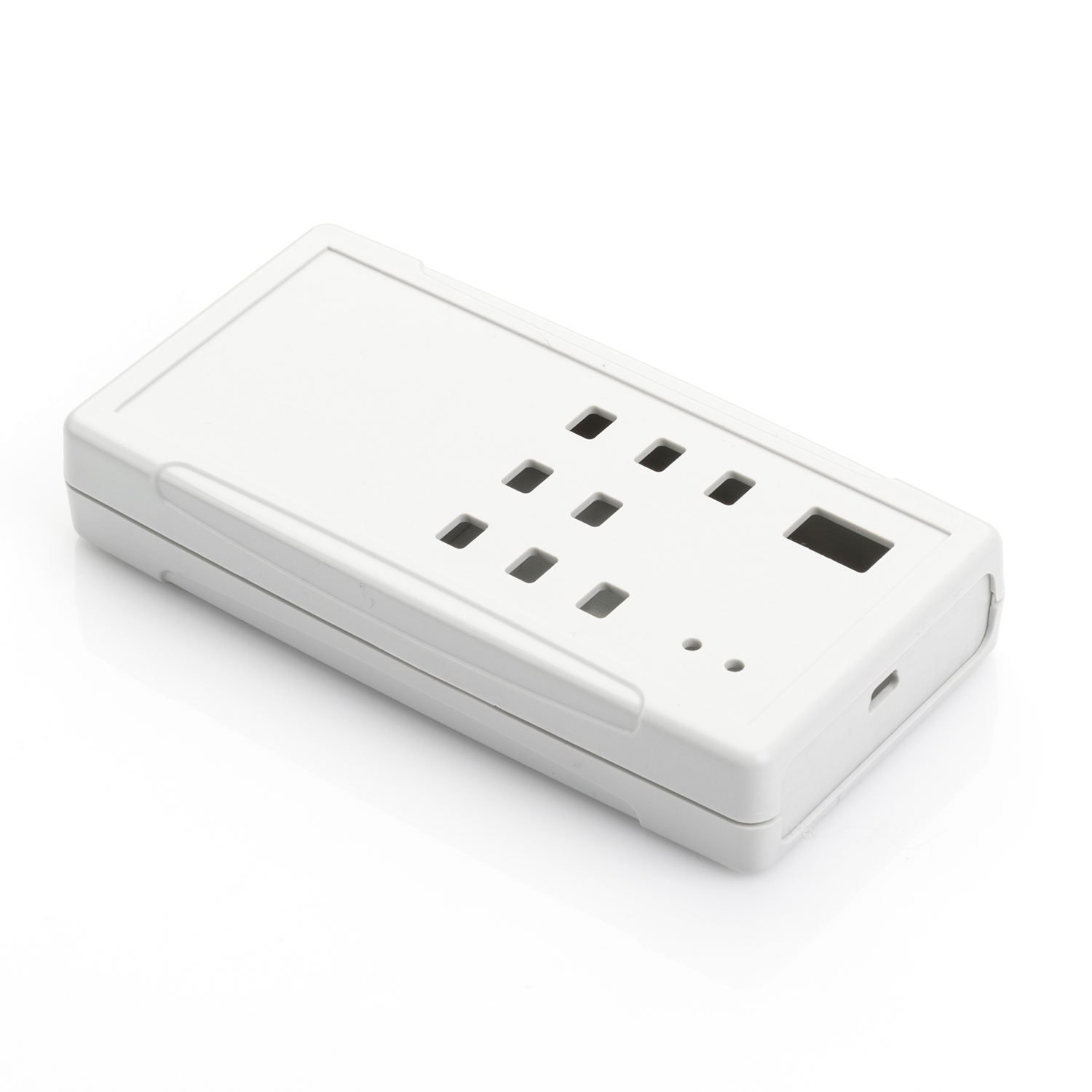
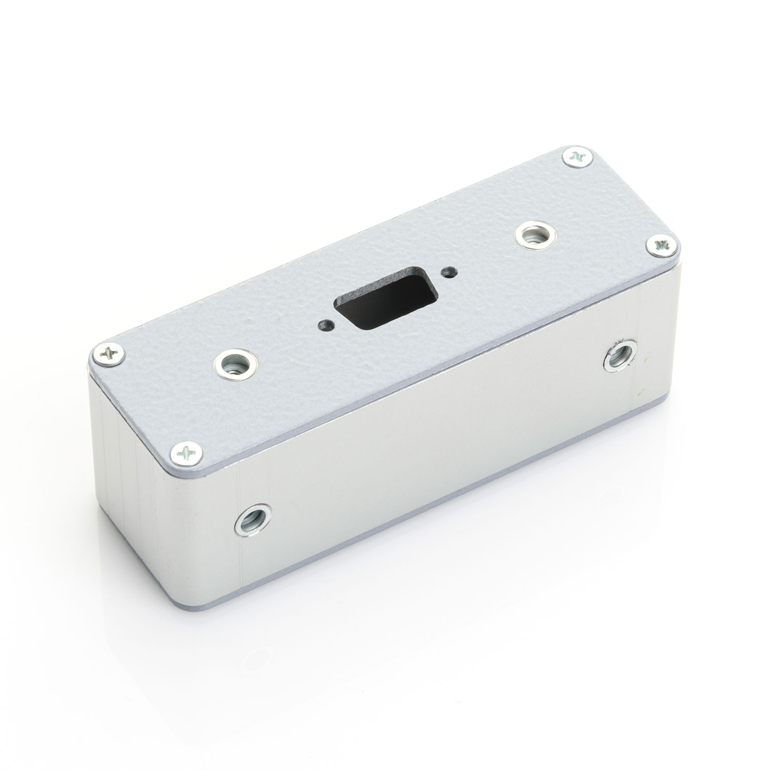
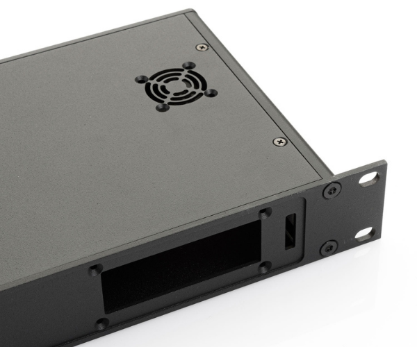
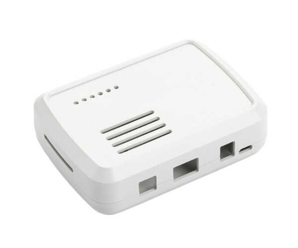
For years, we have been customizing our enclosures as per our customers' requirements. In this regard, attention and accuracy are the key elements for manufacturing our enclosures from raw materials such as plastic, aluminum, extrusion, sheet metal, and aluminum castings.
Thanks to the industrial computer-controlled CNC machines and our lasting experience, all of your components such as circuits, terminal blocks, LCD displays, and keypads easily and precisely fit into our enclosures.
Techical Drawing
Send your PDF, DXF, DWG, STEP or hand-drawn design.
Workmanship
After the technical drawing is approved, the workmanship is started with the product-specific workmanship code (Ex: C-2001-001).
Control
A picture of the finished sample is shared with you and your approval is obtained.
Recieve Your Product
Once your product is ready, it is delivered quickly.
Operation at Every Geometry
We can customize our enclosures with various geometrical shapes and dimensions.
No Minimum Order Quantity
No matter is your order is composed of 1 piece, we are committed to customize it.
Impeccable Worksmanship
With the guidance of our expert staff, we process every surface of your enclosure fast, precise and without any damages.
Cutting Tolerances
We can process your enclosures within ± 0,1 mm of tolerance.
More Than 30 Years of Experience
Our experienced staff will assist you to get the best results.
Technical Support
We provide you with technical support to make sure our product exceeds your expectations.
Waste-Free Production
We cover the potential waste that may result from the production process.
By means of the computer controlled machining, we can process all geometric shapes

Circular Cutting

Curved Cutting

Label Pool Emptying

Flat / Countersunk

Rectangle Cutting

Chamfering
Customized CNC Cutting Code
We save your CNC cutting and UV & Laser printing codes into our systems. Thus, we accelerate our processes once you wish to repeat your previous order.
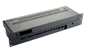
Corner Radius
When a rotating tool is used, the corners of the machining shapes are rounded in proportion to the tool lenght.
Sharper corners are possible using a smaller tool, but this increases our machining time and cost.
| Material | Standart Radius | Minimum Radius |
|---|---|---|
| Plastic | 1,00 mm | 0,75 mm |
| Transparent Panel | 1,25 mm | 1,00 mm |
| Aluminum | 1,25 mm | 1,00 mm |
| Sheet Metal | 1,25 mm | 1,00 mm |
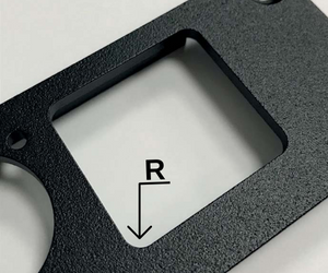
Countersinking
| Size | Countersink Thickness (C) mm | Material Thickness (T) |
|---|---|---|
| M2 | 1,20 mm | 1,20 mm |
| M2,5 | 1,45 mm | 1,45 mm |
| M3 | 1,75 mm | 1,75 mm |
| M3,5 | 2,00 mm | 2,00 mm |
| M4 | 2,30 mm | 2,30 mm |
| M4,5 | 2,55 mm | 2,55 mm |
| M5 | 2,80 mm | 2,80 mm |
| M6 | 3,30 mm | 3,3 mm |
| M8 | 4,40 mm | 4,4 mm |
Countersinking is cutting the top of the screw hole at an angle so that the head of a screw fits on the mounting surface without protruding.
If the countersink thickness of the screw is greater than the thickness of the material to be machined, the excess can be left on the upper or lower surface.
Threading
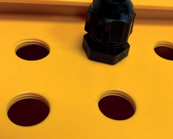
When mounting components such as connectors and cable glands in enclosures we can also thread the enclosure surface with special
tools instead of drilling straight holes and using nuts. You can find the thread lengths and pitches we cut in accordance with PG and Metric
standards in the table
| Measurements | Pitch |
|---|---|
| M2,5 | 0,45 mm |
| M3 | 0,50 mm |
| M4 | 0,70 mm |
| M5 | 0,80 mm |
| M6 | 1,00 mm |
| M7 | 0,50 mm |
| M8 | 0,75 mm |
| M8 | 1,25 mm |
| Measuremets | Pitch |
|---|---|
| M10 | 0,75 mm |
| M10 | 1,00 mm |
| M25 | 1,50 mm |
| M32 | 1,50 mm |
| M40 | 1,50 mm |
| M50 | 1,50 mm |
| M63 | 1,50 mm |
| Measurements | Pitch |
|---|---|
| PG7 | 1,27 |
| PG9 | 1,411 |
| PG11 | 1,411 |
| PG13,5 |
1,41 |
| PG16 |
1,411 |
| PG21 |
1,588 |
| PG29 |
1,588 |
| PG36 |
1,588 |
| PG42 |
1,588 |
| PG48 |
1,588 |
Recessed Area for Membrane Label
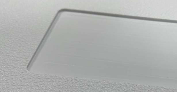 Recessed area at the desired depth
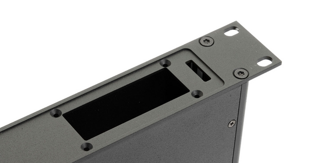 Recessed area can be applied on the metal surfaces
 Enclosures can be machined to stretch
so that switch caps do not puncture the
label
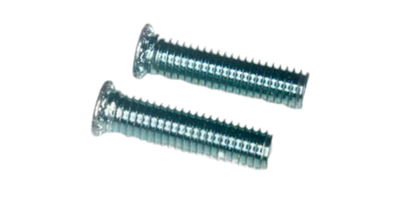
Clinching Fasteners
Fastening nuts, screws and elevation parts are components that enable all kinds of device and card assembly to be made more robust and
durable.
Specially produced fastening nuts, screws and standoffs are pressed into the holes previously drilled on soft metal with a special press
with high pressure.
For aluminum and metal surfaces
Robust and durable
Threaded mounting feet at desired height
Precision work with parallel compression method
High torque resistance
Does not require any extra holes or threads
Reasonable cost and clean workmanship
Screw, Nut, open and closed mounting feet
M3, M4, M5 and M6, M8 sizes
Upgrade Steel Parts (Open) SO Models Compatibility with M3, M4, M5 sizes |
|
|
|
|
Upgrade Steel Parts (Close) BSO Models Compatibility M3, M4, M5 sizes
|
|
|
|
|
Drive in nut (Steel) S Models Compatibility with M3, M4, M5, M6, M8 sizes |
|
|
|
|
Driven Screw (Steel) FH Models Compatibility with M3, M4, M5, M6, M8 sizes |
|
|
|
|


Instructions and File Formats for CNC Cutting
You may send us your instructions about CNC cutting in different ways.
You can send processes you want by drawing manually or on the computer on technical pictures of PDF or DXF format is found on our website.
Hand-drawn or computer-drawn sketch of the process 2/3 dimensional technical drawing. You can also see 2/3 D file formats in table 2.
If you do not have any technical drawings,you are able to send
sample of your product to us. Necessary drawings will be send after
doing according to sample.
During production step, once you send your PCB, and components such as connector, terminals, lcd screen with us, the assembly of the components will be checked then, sizes and tolerances will be corrected for a better performance.
⚠️ Please make sure the file scale is 1/1.
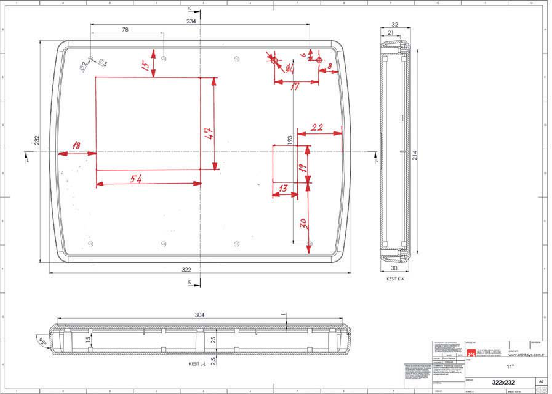
You can share hand drawn sketches on product drawing with us.
| Size | Countersink Thickness (C) mm | Material Thickness (T) |
|---|---|---|
| Hand-Drawn Sketch | 2 Dimensional | pdf, jpg, png, tif |
| Autocad Drawing | 2 Dimensional |
dxf |
| PDF Drawing | 2 Dimensional |
|
| Step | 3 Dimensional |
stp, step |
| Parasolid | 3 Dimensional |
x_t |
| iges | 3 Dimensional |
igs |
Technical Drawing for CNC Cutting
While dimensioning the technical drawing, the center point will be determined first and then the measurement values will be given or the measurements should be made from the points that can be measured with a caliper on the box should be given. The following sample drawings can be
used.
Tolerances
Even though there is a high sensitivity of CNC machines, please avoid giving exact tolerances for plastics as being elastic materials.
Please find general tolerances using the following.
Tolerances DIN7168
| Nominal Dimensions (mm) |
0,5 - 3 | 3 - 6 | 6 - 30 | 30 - 120 | 120 - 400 |
|---|---|---|---|---|---|
| Median | ± 0,1 |
± 0,1 |
± 0,2 |
± 0,3 |
± 0,5 |

